How the game calculates line-of-sight by tracing the gaze vector
One of the core aspects of gameplay in The Sentinel is the ability to "see" things, a concept that applies both to the player and to the many enemies that are scattered around the landscape.
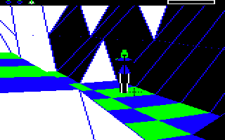
For the player, the concept of "seeing" means moving the crosshair sights around, so that the player's gaze points to whatever is in the middle of the crosshairs. In this example, the crosshairs are pointing at the green tile beneath the robot, so that's what the player can "see":
For the enemies, the concept of "seeing" means working out their current angles of rotation and deciding what they can see from where they are, whether it's tiles or objects. There is also the concept of things being partially visible, when an enemy can see an object but can't see the tile beneath it.
At the heart of both of these processes is the ability to follow a gaze vector; in other words, to calculate the line of sight from the player or enemy into the 3D world. Calculating the gaze vector itself is discussed in the deep dives on the crosshair sights (for the player) and enemy tactics (for enemies); for this deep dive we'll take the gaze vector and follow it through the landscape to see what it can see.
Note that this tracing process is very similar to the ray-casting algorithm that's used to calculate tile visibility for each new landscape view; the main difference is that the tile visibility process ignores any objects on the landscape and interacts with tile shapes in a very simple manner. The gaze vector algorithm described here is based on the same kind of approach, but it is a lot more sophisticated and takes objects and individual tile shapes into consideration. Given this, you might find it useful to browse the deep dive on ray-casting for the tile visibility table to learn about the simpler process first, as that article goes into more detail about the ray-casting aspect, while in this article we'll be concentrating more on the object and tile shape interactions.
Preparing to follow the gaze vector
-----------------------------------
In order to work out what players and enemies can "see", we start by calculating the gaze vector, and then we follow that gaze vector to see what it is pointing at. There are two gaze vectors that we can follow:
- The first is the vector from the player's eyes to the crosshair sights, i.e. the player's gaze. We use this vector in the ProcessActionKeys routine when the player tries to create, absorb or transfer.
- The second is the vector from an enemy's eyes to a specific object, i.e. the enemy's gaze. We use this vector in the CheckEnemyGaze routine to check whether the enemy can see the tile that the object is on, and if that object is a robot (i.e. the player), we also check whether the enemy can see the robot's head, so we can work out whether the player is partially visible to the enemy.
These two cases are subtly different. When tracing the player's gaze we are trying to work out what they can see, but when tracing the enemy's gaze we are trying to work out if they can see a specific object or tile; so the first one takes the gaze vector and works out what's at the end of it, while the second one takes an object and works out whether the gaze vector to that object is obscured. But both calculations use the same ray-tracing approach, so that's what we'll analyse here.
The tracing process is implemented in the FollowGazeVector routine, which takes a scaled-down gaze vector and various configuration options, and follows the vector until it hits something or reaches the edge of the landscape. The approach is the same as in the tile visibility calculations, and that's to step along the gaze vector in small steps, one at a time, and at each step we check where we are along the gaze vector and whether we have bumped into an object or a part of the landscape.
The FollowGazeVector routine expects the gaze vector to have been scaled down already into the small, individual steps that we take along the vector. This scaling process essentially involves passing the 16-bit vector coordinates in this form:
  [ xVector(Lo Bot) ]
  [ yVector(Lo Bot) ]
  [ zVector(Lo Bot) ]
rather than in this form:
  [ xVector(Hi Lo) ]
  [ yVector(Hi Lo) ]
  [ zVector(Hi Lo) ]
as this will divide the gaze vector into small parts, each of which is 1/256 of the full gaze vector. Given that the landscape is made up of 31x31 tiles, this ensures that the vector that is passed to FollowGazeVector is small enough to work as a step that we can incrementally follow along the length of the whole gaze vector.
Before we go through the program flow of FollowGazeVector, we should talk about the GetTileAltitude routine. This routine normally returns the altitude of a tile, along with one bit describing its flatness; a good example of this is when calculating tile visibility, as described in the deep dive on ray-casting for the tile visibility table. However, if the same routine is called with bit 7 of considerObjects set, as it is here, then it does a rather more complex set of calculations, returning the following information rather than a simple altitude:
- (A yPlatformLo): If the tile is flat and contains a boulder or the Sentinel's tower, then this is set to the altitude of the top of the platform object. If there is an object stack, then this will be the altitude of the top of the top boulder on the stack. In other words, the value of (A yPlatformLo) is the altitude of the flat surface on the top of the stack or tower, which is distinct from the altitude of the landscape tile at the bottom or the non-boulder object on top (if there is one).
- A: If the tile is flat and contains a non-platform object then this is set to the high byte of the tile's altitude, which is the same as the high byte of the object's altitude (though the object will have a low byte as well that determines its height above the tile). If the tile is not flat then this is set to the tile altitude from the tile data, which will be the altitude of the tile anchor, i.e. the front left tile corner.
- C flag: This returns the tile's flatness, and is clear if the tile is flat or set if the tile is not flat.
- boulderOnTile: This has bit 7 set if the tile contains a boulder.
- targetOnTile: This has bit 7 set if the tile contains the target object (i.e. the object number specified in targetObject).
- gazeCanSeeTree: This has bit 7 set if the tile contains a tree that can be seen by the gaze vector.
- considerObjects: This has bit 6 set if the tile contains a boulder or the Sentinel's tower and the current position along the gaze vector is not horizontally within the platform object (so the gaze vector is passing close by the platform object but is not hitting it).
- yAccuracyLo: This is changed from the default value of 128 to 16 if the tile contains the Sentinel's tower and the gaze vector is pointing at the sides of the tower. We can then use this to prevent the sides of the tower acting like the sides of a boulder (so you can't absorb the Sentinel by pointing at the sides of the Sentinel's tower).
A lot of this extra data is easy enough to calculate, but the most complex parts of the above analysis are the calculations for the boulderOnTile and gazeCanSeeTree flags. These both call the CheckForTileCentre routine to work out the horizontal distance from the tile centre to the gaze vector, and then they compare that with the shape of the boulder or tile.
The boulderOnTile calculation is relatively straightforward, simply requiring the horizontal distance to be within 50% of the tile centre, but things get more complicated for the gazeCanSeeTree calculation. For this part, we first check whether the vector is within the correct vertical range for the tree, making sure to include any boulders beneath the tree. If it is in the correct vertical strip, we then compare these values:
- The horizontal distance from the centre of the tile (i.e. from the centre of the trunk) to the gaze vector
- The vertical height difference between the gaze vector and the top of the tree, divided by 4
If the horizontal distance is less than the vertical difference, then the gaze vector is deemed to be inside the tree, so we register a hit and set bit 7 of gazeCanSeeTree. In this way, gazes that land on the lower parts of the tree can be further from the centre point than gazes that land on the upper parts of the tree, while still being considered gazes that can see the tree.
Now that we have all this extra information about the tiles we're going to be gazing at, let's analyse how the FollowGazeVector routine works.
Following the gaze vector
-------------------------
Before we look at the innards of the FollowGazeVector routine, let's be clear about what it's looking for. The purpose of the routine depends on bit 7 of enemyCheckingRobot:
- If bit 7 of enemyCheckingRobot is clear, then the routine works out whether the gaze vector can see a tile that can be interacted with, or the side of a boulder that can be interacted with (i.e. the top boulder on a stack).
- If bit 7 of enemyCheckingRobot is set, then the routine does the same calculation, but it will return a positive response even if the enemy is at a lower altitude than the target. The CheckEnemyGaze routine calls FollowGazeVector twice, once with bit 7 set and a target of the robot's head, and once with bit 7 clear and a target of the robot's tile. This lets us detect partial visibility of robots, i.e. when the enemy can see a robot's head but not the tile that it's on.
Given the correct value of enemyCheckingRobot and the scaled-down gaze vector as arguments, let's analyse how the ray-tracing process works in part 1 of FollowGazeVector (we'll cover parts 2 to 5 in the next section).
First we fetch the Cartesian coordinates of the viewing object (i.e. the player or enemy) to use as a starting point. This will actually be the coordinates of the viewing object's eyes, as objects are spawned at a height of 0.875 tiles above the tiles they are on, to represent the object's eye level, so this ensures we start our calculation from the viewer's eyes.
We then step along the line of sight from the viewer's eyes by taking the start coordinates and adding the scaled-down gaze vector for each step, so we work our way along the full gaze vector, moving 1/256 of the way along the entire vector in each step. At each new step, we check the following:
- If we have fallen off the edge of the landscape then return from the subroutine with the C flag set to indicate that the viewer is not looking at a tile. This will never happen when tracing an enemy gaze as the enemy's gaze vector is always traced in the direction of an object, but it can happen if the player presses the create, absorb or transfer buttons while they are gazing beyond the edges of the landscape.
- Call GetTileAltitude with bit 7 of considerObjects set to extract lots of data about the tile that's at the same x- and z-coordinates as the current position along the gaze vector (so that's all the data listed above). This tile may be above or below the gaze vector, it just shares the same vertical space as our current position.
- If the tile shape at this point along the gaze vector is not flat, then jump to part 2 of FollowGazeVector to calculate the gaze vector's interaction with the tile slopes (we'll look at this part of the process in the next section).
- If we get here then the gaze vector is sharing vertical space with a flat tile, so we now check whether it is passing above or far below the tile surface:
- If the gaze vector hasn't hit the tile and is still passing through empty space above the landscape, then loop back to move along the gaze vector by another step and restart the checks.
- If the gaze vector is passing below the bottom of the "tile cube" that has the flat tile surface on its top or that contains the top of the platform, then this means the gaze must have passed deep into the ground beneath the tile, so return from the subroutine with the C flag set to indicate that the viewer is not looking at a tile.
- If we get here then the gaze is currently sitting within a "tile cube", as follows:
- If the tile does not contain a boulder, then we are within the "tile cube" that contains the tile's surface, i.e. the cube just below the surface, with the flat as the top surface of the cube.
- If the tile contains a boulder, we are within the "tile cube" that contains the boulder's surface.
- If the call to GetTileAltitude indicated that the tile contains a boulder or the Sentinel's tower, and the gaze vector is not within the boulder or tower, then the gaze is passing very close to the tower or boulder but is just missing it. In this case we consider any tiles further along the gaze vector to be obscured, so return from the subroutine with the C flag set to indicate that the viewer is not looking at a tile.
- If we are looking for a tile as opposed to a robot (i.e. if bit 7 of enemyCheckingRobot is clear) and we are not looking at a boulder (i.e. the call to GetTileAltitude indicated that the tile does not contain a boulder), then we check whether the tile is above the viewer. If the tile is above the viewer, then the viewer won't be able to see the tile surface, so return from the subroutine with the C flag set to indicate that the viewer is not looking at a tile.
- If we get here then the viewer's gaze has either landed on a tile or the side of a boulder they can interact with, so the final check is to make sure the viewer is not looking at their own tile. If they are looking at their own tile, then return from the subroutine with the C flag set to indicate that the viewer is not looking at a suitable tile for interaction. However, if they aren't looking at their own tile, then we have a winner, so return from the subroutine with the C flag clear to indicate that the viewer is looking at a suitable tile or the side of a suitable boulder.
That's the process for following the gaze vector and landing on flat tiles, boulder sides and objects, so now let's consider what happens when the gaze vector hits a non-flat tile shape.
Dealing with tile shapes
------------------------
The interaction between the gaze vector and non-flat tile shapes is calculated in parts 2 to 5 of FollowGazeVector. We consider jumping here after fetching the extended tile data from GetTileAltitude in part 1, which tells us the shape of the tile that's in the same vertical space as our current position along the gaze vector. If the shape is non-zero (i.e. not flat), then we jump to part 2 and the four remaining parts of the routine take over.
Here's an overview of these four parts:
- Part 2: Calculate the altitudes of the four corners in a non-flat tile.
- Part 3: Calculate whether the viewing object's gaze is obstructed by a tile of shape 4 or 12 (i.e. a tile with one horizontal edge).
- Part 4: For non-flat tiles with two horizontal edges, work out which tile edge to use when checking for obstruction of the gaze vector.
- Part 5: For non-flat tiles with two horizontal edges, work out whether the tile edge obstructs the gaze vector.
The first two parts are pretty simple. Part 2 just fetches the altitudes of the four corners in the tile shape, by calling GetTileAltitude with bit 7 of considerObjects clear to fetch the altitudes into variables S, T, U and V as follows:
     ^           [T]  [U]
     |
     |           [S]  [V]
  z-axis
   into
  screen      x-axis from left to right --->
This is consistent with the way we calculate tile shapes in the first place; see the deep dive on tile shapes for details. The tile shapes deep dive also contains images of the different tile shapes, so you might want to refer to these when reading about the different shapes in the rest of this section.
Dealing with irregular shapes
-----------------------------
If the tile shape is 4 or 12, then the tile has one horizontal edge with the other two points being arbitrary (but not at the same height as the horizontal edge). Here are two examples of the kind of shape we're talking about:
Note that these two shape numbers cover a whole collection of variations, so these are just examples.
For all these kinds of uneven tile shape, we fall through into part 3. This does a pretty simple calculation to work out whether the gaze vector is being obstructed by the tile: if the current position along the gaze vector is below the height of at least one tile corner, then we consider this to be enough potential interference to be blocking the viewer's gaze of any tiles that might be partially visible beyond; otherwise we consider the vector to be passing above the tile shape, and we can continue tracing.
This algorithm errs on the side of caution and effectively blocks any line of sight that might potentially be interfered with. For example, you might be able to glimpse things beyond this kind of tile shape if you happened to be staring down the line of the gully from a height, but this would be difficult to calculate, so it's better to be cautious than allow players and enemies to stare through the uneven ground.
If the gaze is deemed to be blocked by the tile, we return from the subroutine with the C flag set to indicate that the viewer is not looking at a tile; otherwise we jump back to part 1 to keep on tracing.
Identifying the slopes in slopes, ridges and gullies
----------------------------------------------------
If the tile shape isn't 4 or 12, then we jump to part 4. By this point we know that the shape must have two horizontal edges; those edges can either be opposite each other, as in the case of a single-face slope, or they can be adjacent to each other, as in the case of a ridge or gully.
Here are the kinds of tile shape we are talking about, with single-face slopes looking like this, with the horizontal edges being opposite each other:
Gullies, meanwhile, look like this, with the horizontal edges being adjacent to other:
Ridges also have their horizontal edges adjacent to other:
For these shapes, the calculation is rather more complex. The idea is to work out where the gaze vector is relative to the general slope of the tile, and then use this to work out what the height of that slope is at the point where the gaze vector is passing through the shape, so we can work out whether the vector is above or below the surface of the shape.
The task in part 4 is to work out which edge of the shape contains a suitable slope for our calculation; part 5 will then use this to work out where the gaze vector is in relation to this slope.
For shapes with a single-face slope (i.e. shapes 1, 5, 9 and 13), the choice is relatively straightforward: we just need to work out which side contains the slope. There are two sloping sides in this shape, and they contain identical slopes, so it doesn't matter which one we pick, so the code chooses either the left or top edge, depending on the shape (specifically, it chooses the left edge for shapes 1 and 9, and the top edge for shapes 5 and 13). This is then passed to part 5 for analysis.
For shapes with two-face slopes (i.e. shapes 2, 3, 6, 7, 10, 11, 14 and 15), it's a bit trickier. The algorithm works out which two edges are sloping via a set of conditionals and branches that breaks down the shape number into a value in A between 0 and 3, and it then works out which of those edges is closest to the current position along the gaze vector.
The table at tileEdges table helps us do this. This table is made up of two numbers for each pair of edges represented by the value of A; these are the corner numbers at the start of each of the two edges in the pair, so for each value of A, we need to choose one of the corner numbers from the pair to pass to part 5. We choose the correct value according to whether the gaze vector is closer to the edge along the x-axis or the z-axis.
This is all a bit hard to follow, so let's consider an example. Take tile shape 2, for which we will have calculated A = 0 to denote that the bottom and left edges are the sloping edges in this shape, which looks like this:
The red face points towards the front of the landscape, and the tileEdges table contains 0 and 3 for this shape (to denote the left and front edges respectively, i.e. the edges along the bottom of the green and red faces in the image above).
Zooming in on the tile, we have the following, where the edge between [0] and [3] is along the front of the shape, i.e. along the bottom of the red face (so the gully goes from [2] at the top down to [0] at the bottom). If [x] is the current position along the gaze vector, then we get this view when looking at the tile shape from above:
[1]                 [2]
 | xCoordLo
 |<--------> [x]
 |            ^
 |            |
 |            |  zCoordLo
 |            v
[0] --------------- [3]
We can work out which edge is nearest to the gaze vector by comparing xCoordLo and zCoordLo from the above diagram, so the calculation is:
- If xCoordLo < zCoordLo, we pick the first entry from tileEdges, i.e. 0, which is the left edge (because the gaze point in [x] is closer to the left edge than the bottom edge).
- If xCoordLo >= zCoordLo, we pick the second entry from tileEdges, i.e. 3, which is the bottom edge (because the gaze point in [x] is closer to the bottom edge than the left edge).
The comparison is flipped around for tiles where the slopes are along the top and left edges, or along the bottom and right edges. In these cases we compare ~xCoordLo instead of xCoordLo, as in this example when the slopes are along the bottom and right edges:
[1]                 [2]
           ~xCoordLo |
      [x] <--------> |
               ^     |
               |     |
     zCoordLo  |     |
               v     |
[0] --------------- [3]
So we've now identified which of the sloping edges is the closest to the gaze vector, so we can now pass this to part 5 to work out whether the shape is blocking the gaze vector.
Testing for collisions with slopes, ridges and gullies
------------------------------------------------------
Part 5 of FollowGazeVector takes the number of the sloping edge from part 4 and calculates whether the gaze vector passes above or below this slope. Here's how it works.
We start by calculating the distance along the tile edge that corresponds to the current position of the gaze vector. To see how this works, consider the axes of the tile corners:
   ^           [1]  [2]
   |
   |           [0]  [3]
z-axis
 into
screen      x-axis from left to right --->
The low bytes of the current gaze vector in xCoordLo and zCoordLo give us the fractional part of the coordinate of the current position along the gaze, and the fractional part gives us the position of the coordinate within the tile (as the tile corners are on the integer coordinates).
Zooming in on the tile, we have the following, where [x] is the current position along the gaze vector when looking at the tile from above:
[1]                 [2]
  xCoordLo
<----------> [x]
              ^
              |
              |  zCoordLo
              |
[0]           v     [3]
We now set the edgeGazeDistance variable to the corner-relative coordinate of the gaze vector along the edge that we are considering (so if we are examining the edge from corner X to corner X + 1, we're looking for the distance between corner X and the [x] of the gaze vector).
For example, if we are considering the left edge from 0 to 1, the distance of the [x] relative to corner 0 and along the edge is zCoordLo, while on the top edge from 1 to 2, the distance of the [x] relative to corner 1 and along the edge is xCoordLo.
The other two edges are similar but the distances are in the opposite direction to the axes. So if we are considering the bottom edge from 3 to 0, the distance is ~xCoordLo, because:
xCoordLo + ~xCoordLo = 1
So adding xCoordLo and ~xCoordLo together gives us the distance between the tile corners (which is 1), so it follows that ~xCoordLo is the distance from corner 3 to the gaze point, as xCoordLo is the distance from corner 0 to the gaze point.
We now set edgeGazeDistance to the correct value, depending on the edge number we passed to the routine in A:
- edgeGazeDistance = zCoordLo if A = 0
- edgeGazeDistance = xCoordLo if A = 1
- edgeGazeDistance = ~zCoordLo if A = 2
- edgeGazeDistance = ~xCoordLo if A = 3
So edgeGazeDistance contains the fractional distance along the edge that corresponds to the current position along the gaze vector. We can now use to calculate where the gaze vector crosses the edge.
The next step is to calculate the gradient of the slope, which we can do easily enough by subtracting the altitudes of the two tile corners at each end of the edge. We then calculate the following:
(A T) = fractional distance * gradient
To recap, the fractional distance is a fractional value that represents how far along the edge we would need to go in order to be at the coordinate that corresponds to the current position along the gaze vector. The gradient is the change in altitude as we move from one end of the edge to the other, so multiplying these two therefore gives us the height of the point along the edge that corresponds to the current position along the gaze vector.
This height is relative to the tile corner at the start of the edge, so to get the altitude of the point in the 3D world, we need to add the result in (A T) to the altitude of that corner. This gives us the global altitude of the point along the edge that corresponds to the current position along the gaze vector.
Now for the final stage: working out whether the edge is blocking the gaze vector, which we do as follows:
- If the current position along the gaze vector is higher than the corresponding point on the edge, then the viewer's gaze is not being obstructed by the edge, so we can jump back to part 1 and continue moving along the gaze vector.
- Otherwise the current position along the gaze vector is below the corresponding point on the edge, so the viewer's gaze is being obstructed by the edge, so we return from the subroutine with the C flag set to indicate that the viewer is not looking at a suitable tile, or that the view of the robot is blocked.
And that's how the code works out whether the various tile shapes are blocking the gaze vector or allowing it to pass overhead unscathed.